
Straight heaters
Product overview
- Power up to 30 kW per heating element
- Watt density from 0.1 to 20 W/cm²
- Voltage max. 750 V
Advantages
- Reliability and robustness of the heating element. High quality raw material.
- Large range of materials and options according to customer process and conditions of use.
- Benefit from CETAL’s 50 years of experience as designer and manufacturer!
Operating conditions
- Normal (non-ATEX)
- Hazardous areas (ATEX/IECEx) and NEC 505
- Fluid/solid: from -270 °C (3 K) to 1000 °C
- Corrosive environment
Water
- Stagnant water, max load 8 – 12 W/cm², material: copper, 321, 316L
- Circulating water, max load 10 – 16 W/cm², material: copper, 316L, incoloy 800, incoloy 825
- Boric water, max load 8 W/cm², material: 316L
- Boiler water, max load 8 – 16 W/cm², material: 316L, incoloy 800, incoloy 825
- Chlorated water, max load 6 W/cm², material: incoloy 825
- Sea water, max load 3.5 – 6 W/cm², material: incoloy 825, inconel 600
- Demineralized water / deionized / distilled / softened, max load 4 – 6 W/cm², material: 316L, incoloy 800, incoloy 825
- Domestic hot water, max load 4 – 8 W/cm², material: copper, 316L, incoloy 825
- Caustic water (2%, 10%, <30%, 70%), max load 2.3 – 7 W/cm², material: 316L, incoloy 825, inconel 600
Oil
- Fuel oil pre-heating, light fuel oil, C fuel oil, max load 1 – 2 W/cm², material: 321, 316L
- Heavy fuel, max load 0.5 – 3.5 W/cm² acc to grade, material: 316L
- Gasoline, kerosene, max load 3 – 3.5 W/cm², material: 316L
- Machine oil SAE 10, 30, 40 & 50, max load 2 – 3.5 W/cm², material: 316L
- Mineral oil , max load 0.5 – 3.5 W/cm² acc to temp, material: 321, 316L
- Lube oil, max load 2.3 W/cm², material: 321, 316L
Acid & corrosive fluid
- Acetic acid, max load 6 W/cm², material: 316L, incoloy 825
- Boric acid, max load 6 W/cm², material: incoloy 825
- Chloric, hydrofluoric, nitric, sulphuric acid, max load 1.5 W/cm², material: teflon coat
- Boric acid, max load 6 W/cm², material: incoloy 825
- Alkaline bath, max load 6 W/cm², material: 321 (no corrosive compound), 316L
- Phosphate bath, max load 4 W/cm², material: 316L, incoloy 825
Glycol
- Ethylene glycol, propylene glycol, 4 – 8 W/cm² acc. to concentration, material: 321, 316L
Others
- Asphalt, tar, and other heavy or highly viscous compounds, max load 0.5 – 1.5 W/cm², material: 316L
- Milk, max load 0.3 W/cm², material: 316L
Gas
- Air, max load 0.1 – 8 W/cm² acc. to sheath temp., material: 321
- Circulating air, max load 0.1 – 8 W/cm² acc to sheath temp., material: 309
- Natural gas, max load 0.1 – 8 W/cm² acc. to sheath temp., material: 321, 316L
- Argon, nitrogen, load acc. to sheath temp., material: 321, 316L, incoloy 825, inconel 600
- Propan, butane, load acc. to sheath temp., material: 321, 316L
- Oxygen, hydrogen, load acc. to sheath temp., material: 316L
Solids
- Aluminium, brass, bronze cast in, max load 4 – 15 W/cm², material: 309
- Copper-nickel cast in, max load 5 – 10 W/cm², material: 309
- Oxychloration, max load 3 W/cm², material: incoloy 800, incoloy 825
- Calcination, max load 3 W/cm², material: incoloy 800, incoloy 825
- HC regeneration, max load 2 W/cm², material: incoloy 800, incoloy 825
Technical description
The watt density, tube diameter and the tube sheath are chosen to optimize the reliability and robustness (corrosion, temperature) of CETAL equipments.
Technologies
- Tubular heating element
Tube diameter & material
- Tube diameter: 6.5 / 8.5 / 10 / 13.5 / 16 mm
- Tube material:
- Stainless steel: AISI 321 (1.4541) / AISI 316L (1.4404) / AISI 309 (1.4828)
- Others: Incoloy 800 (1.4876) / Incoloy 825 (2.4858) / Inconel 600 (2.4816)
- Titanium
- Specific coating: Teflon™ (PTFE) / Halar®
- Tube type: sealed tube, seamless tube (on request)
Manufacturing
- 100% of the components come from our high-quality suppliers from Europe
- 100% manufacturing in CETAL factory
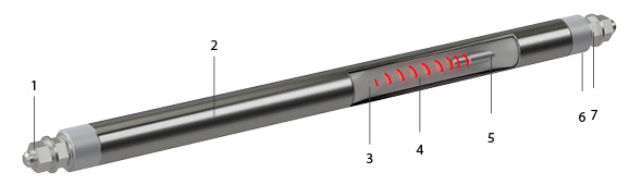
- Connection terminals
- Tube
- Insulation : magnesia oxyde (Mg O), to secure optimized heat transfer and electrical insulation.
- Resistance wire: Made of Nickel Chrome 80/20, it is the active part of the heating element (Joule effect)
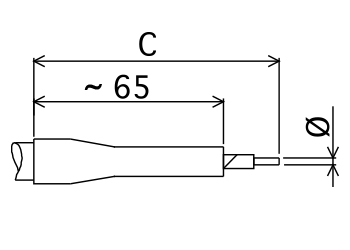
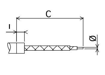
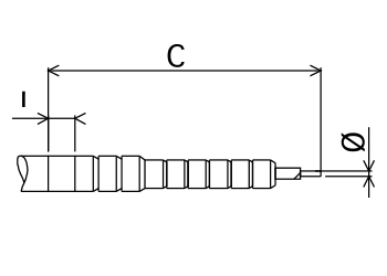
- Cold length
- Sealing material: Keeps out external moisture. Different types (silicon, resins, cement) are used depending on the industrial application, the external medium and temperature
- Output insulation: Made of steatite ou corundum, it provides dielectric insulation (creepage distance, distance in the air).
CETAL offers a large range of non heating parts / cold parts to meeting any customer specification.
The table below shows the different cold parts available by diameter and length.
| Tube Ø | 6,5 | |||||||||
|---|---|---|---|---|---|---|---|---|---|---|
| 8,5 | ||||||||||
| 10 | ||||||||||
| 13,5 | ||||||||||
| 16 | ||||||||||
| Ø tige de sortie | Ø 2 | Ø 3,5 | M4 x 0,7 | M5 x 0,8 | M6 x 1 | M8 x 1,25 | ||||
| Lg NCH | Matière Acier | Matière Inox | Matière Acier | Matière Inox | Matière Acier | Matière Inox | Matière Acier | Matière Inox | Matière Acier | |
| 35 | ||||||||||
| 40 | ||||||||||
| 45 | ||||||||||
| 55 | ||||||||||
| 75 | ||||||||||
| 65 | ||||||||||
| 95 | ||||||||||
| 105 | ||||||||||
| 135 | ||||||||||
| 150 | ||||||||||
| 180 | ||||||||||
| 205 | ||||||||||
| 200 | ||||||||||
| 225 | ||||||||||
| 235 | ||||||||||
| 260 | ||||||||||
| 300 | ||||||||||
| 330 | ||||||||||
| 365 | ||||||||||
| 415 | ||||||||||
| 420 | ||||||||||
| 445 | ||||||||||
| 500 | ||||||||||
| 505 | ||||||||||
| 530 | ||||||||||
| 620 | ||||||||||
| 775 | ||||||||||
| 800 | ||||||||||
| 1000 | ||||||||||
| 1340 | ||||||||||
| Materials | |||||||
| Copper | Austenitic steel | Nickel alloy | |||||
| AISI code | 321 | 316 L | 309 | INCOLOY 800 | INCOLOY 825 | INCONEL 600 | |
| DIN code | 1.4541 | 1.4404 | 1.4828 | 1.4876 | 2.4858 | 2.4816 | |
| Usuals diameters | |||||||
| 6,5 | |||||||
| 8,5 | |||||||
| 10 | |||||||
| 13,5 | (1) | ||||||
| 16 | (1) | (1) | |||||
| limit temperature of use | |||||||
| 250 °C in the air | 750 °C | 750 °C | 1000 °C | 950 °C | 950 °C | 950 °C | |
(1) Seamless tube on stock
| Tube diameter | Max voltage |
| 6.5 | 400V |
| 8.5 | 415V |
| 10 | 500V |
| 13.5 | 690V |
| 16 | 750V |
- Wire restance tolerance: -5% and +10% of the nominal resistance value
- Power tolerance < 100W: -/+10%
- Power tolerance > 100W: +5% – 10%
|
Sheaths |
Very high quality rolled, welded or seamless tube manufactured and inspected according to standards ASTM-DIN ou NFA 49-147 |
|||
|
Forming |
The heating elements are available in a variety of shapes adapted to the use circumstances defined in the specifications or by the customer |
|||
|
Tolerances |
Diameter: |
6.5 ± 0.1 mm |
13.5 ± 0.1 mm |
|
|
8.5 ± 0.1 mm |
16 ± 0.1 mm |
|||
|
10 ± 0.1 mm |
||||
|
Length: |
± 1 % with + 5 mm minimum |
|||
|
Standard material: |
The dimensions in the table are maximal Dimensions intended to prevent assembly problems |
|||
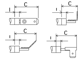
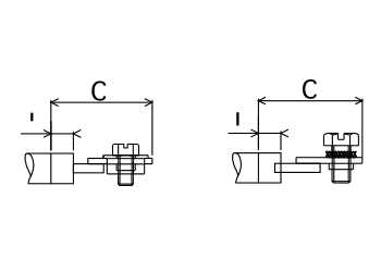
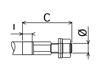
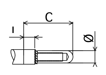
Type B 100
- THREADED STEEL OR STAINLESS STEEL ROD
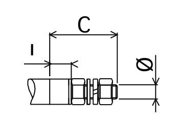
| Dimensions | Sheaths Ø | ||||||
| Ø mm | C | I | 6.5 | 8.5 | 10 | 13.5 | 16 |
| M4 x 0.7 | 20 | 5 | |||||
| M4 x 0.7 | 20 | 5 | |||||
| M4 x 0.7 | 20 | 5 | |||||
| M5 x 0.8 | 30 | 10 | |||||
| M5 x 0.8 | 30 | 10 | |||||
| M6 x 1 | 35 | 10 | |||||
| M6 x 1 | 35 | 10 | |||||
| M8 x 1.25 | 35 | 10 | |||||
| M8 x 1.25 | 35 | 10 | |||||
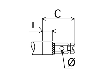
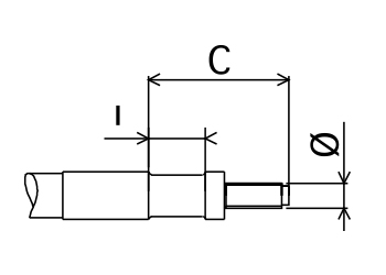
Type B 200
- PLAIN ROD
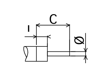
| Dimensions | Sheaths Ø | ||||||
| Ø mm | C | I | 6.5 | 8.5 | 10 | 13.5 | 16 |
| 2 | 20 | 5 | |||||
| 3.5 | 25 | 5 | |||||
Type B 300
- BRAID OR CABLE
| Dimensions | Sheaths Ø | |||||
| section mm² | C | 6.5 | 8.5 | 10 | 13.5 | 16 |
| PVC INSOLATED COPPER CABLE H07VK 70°C | ||||||
| 1.5 | (1) | |||||
| 2.5 | (1) | |||||
| RUBBER INSOLATED COPPER H07RNF 85°C | ||||||
| 1.5 | (1) | |||||
| 2.5 | (1) | |||||
| 4 | (1) | |||||
| 1.5 | (1) | |||||
| 2.5 | (1) | |||||
| 4 | (1) | |||||
| 6 | (1) | |||||
| 10 | (1) | |||||
| SILICONE INSOLATED COPPER 180°C | ||||||
| 1.5 | (1) | |||||
| 2.5 | (1) | |||||
| 4 | (1) | |||||
| 6 | (1) | |||||
| GLASS BRAIDED COPPER 280°C | ||||||
| 1 | (1) | |||||
| 1.5 | (1) | |||||
| 2.5 | (1) | |||||
| 4 | (1) | |||||
| 6 | (1) | |||||
| INSOLATED NICKEL WIRE 700°C | ||||||
| 1.5 | (1) | |||||
| 2.5 | (1) | |||||
| 4 | (1) | |||||
| 6 | (1) | |||||
(1) Cable lenght go request
| Dimensions | Sheaths Ø | |||||
| section mm² | C | 6.5 | 8.5 | 10 | 13.5 | 16 |
| NICKEL BRAIDED NICKEL 350°C / 450°C | ||||||
| 1 | (1) | |||||
| 2.5 | (1) | |||||
| 2.5 | (1) | |||||
| 4 | (1) | |||||
| 6 | (1) | |||||
(1) Cable lenght go request
| Dimensions | Sheaths Ø | |||||
| section mm² | C | 6.5 | 8.5 | 10 | 13.5 | 16 |
| CERAMIC NICKEL WIRE | ||||||
| 1.5 | (1) | |||||
| 2.5 | (1) | |||||
(1) Cable lenght go request
Type B 400
- 6,35 TAB
| Dimensions | Sheaths Ø | ||||
| Description | C | I | 6.5 | 8.5 | 10 |
| Straight single | 25 | 5 | |||
| carved single | 23 | 5 | |||
| Transverse single | 15 | 5 | |||
| Straight twin | 22 | 5 | |||
| Delta twin | 22 | 5 | |||
Type B 500
- FLAT TERMINAL
| Dimensions | Sheaths Ø | |||||
| C | I | 6.5 | 8.5 | 10 | 13.5 | 16 |
| 25 | 5 | |||||
| 30 | 10 | |||||
Type B 600
- THREADED TERMINAL
| Code | Dimensions | Sheaths Ø | ||||
| Ø mm | C | I | 6.5 | 8.5 | 10 | |
| LAITON : B 614-6 | M6 x 1 | 30 | 5 | |||
| INOX : B 623-6 | M6 x 1 | 21 | 5 | |||
Type B 700
- SCREW TYPE BRASS TERMINAL
| Dimensions | Sheaths Ø | |||
| C | I | 6.5 | 8.5 | 10 |
| 15 | 5 | |||
Type B 800
- BRAZABLE STEATITE
| Dimensions | Sheaths Ø | ||||||
| Ø mm | C | I | 6.5 | 8.5 | 10 | 13.5 | 16 |
| M 6 | 37 | 13 | |||||
| M 6 | 37 | 13 | |||||
| M 8 | 55 | 15 | |||||
| Use in humid conditions | watertight | ||||||
| temperature from – 60°C to + 200°C | |||||||
| defrosting resistance | |||||||
Type B 900
- BRASS PIN TERMINAL
| Dimensions | Sheaths Ø | ||||||
| Ø mm | C | I | 6.5 | 8.5 | 10 | 13.5 | 16 |
| 6 | 22 | 5 | |||||
| 6 | 22 | 5 | |||||
- According to CE European directives and CE market (for Europe)
- ATEX/IECEx certificate for component or system
- EAC CU TR, c CSA us (NEC 505)
![]()
Electrical tests
- Power test by cold resistance measurement. Allowed tolerance: -5% and +10% of the nominal resistance value.
- Insulation test, direct voltage 500 V, mini cold value is > 100 Megohms
- Dielectric test, (2U + 1000 V) x 1,2 during 1 second
- The stray current and the hot dielectric rigidity can be measured on a sample at operating temperature (on request).
- 100% of the heating elements are tested before shipment (final control)
Mechanical tests
- Visual inspection
- X-ray test (if required)
Dimensional test
- Critical dimensions are tested
- Marking: specific customer marking on each heating element
- Specific connection terminals (on request)
- Fixing part such as connectors (on request)
CETAL deliver straight heating elements to many customers in different industries where the reliability and the quality is a must.
The heating element being the active part (“engine”) of the final product or within the customer process, our customer make the choice of reliability!
