

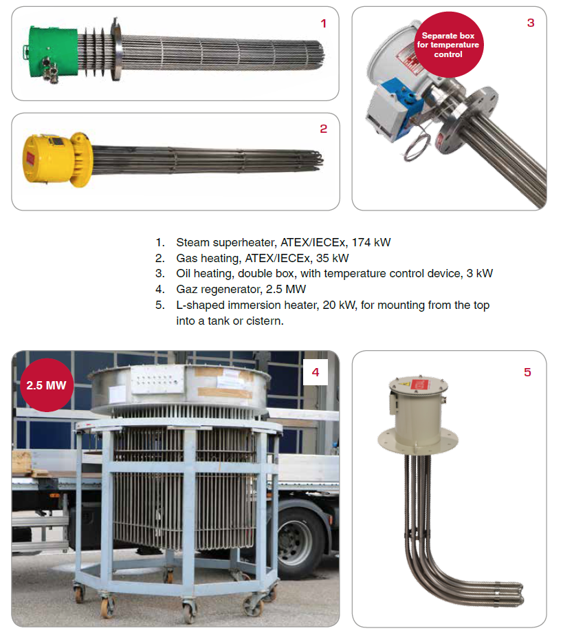
Flange immersion heaters
Product overview
- Power up to 5 MW (5 000kW)
- Watt density from 0.1 to 20 w/cm²
- Process temperature up to +650 °C
- Voltage max. 690 V
Advantages
- Large range of materials and options according to customer process and conditions of use
- Benefit from CETAL’s 50 years of experience as designer and manufacturer!
- Equipment available for use in hazardous areas or safe environment
- The end-to-end control of the design and production chain allows us to deliver a product which suits your process perfectly
Operating conditions
- Normal (non-ATEX)
- Hazardous areas (ATEX/IECEx) and NEC 505
- Extreme environments: -60°C to + 80 °C
- Fluid/solid: from -270 °C (3 K) to 1000 °C
- Onshore / Offshore environment
- Salt atmosphere
- Pressure: 250 bars (PED)
Water
- Stagnant water, max load 8 -12 W/cm², material: copper, 321, 316L
- Circulating water, max load 10 -16 W/cm², material: copper, 316L, inc 800, inc 825
- Boric water, max load 8 W/cm², material: 316L
- Boiler water, max load 8 -16W/cm², material: 316L, inc 800, inc 825
- Chlorated water, max load 6 W/cm², material: inc 825
- Sea water, max load 3.5 -6 W/cm², material: inc 825, inc600
- Demineralized water / deionized / distilled / Softened,max load 4 -6 W/cm², material: 316L, inc 800, inc 825
- Domestic hot water, max load 4 -8 W/cm², material: copper, 316L, inc 825
- Caustic water (2%, 10%, <30%, 70%), max load 2.3-7W/cm², material: 316L, inc 825, inc 600
Oil
- Fuel oil pre-heating,light fuel oil, C fuel oil, max load 1 -2 W/cm², material: 321, 316L
- Heavy fuel, max load 0.5 -3.5 W/cm² acc. to grade, material: 316L
- Gasoline, kerosene, max load 3.0-3.5 W/cm², material: 316L
- Machine oil SAE 10, 30, 40 & 50, max load 2.0-3.5 W/cm², material: 316L
- Mineral oil , max load 0.5 -3.5 W/cm² acc to temp, material: 321, 316L
- Lube oil, max load 2.3 W/cm², material: 321, 316L
Acid & corrosive fluid
- Acetic acid, max load 6W/cm², material: 316L, inc 825
- Boric acid, max load 6W/cm², material: inc 825
- Chloric, hydrofluoric, nitric, sulphuric acid, max load 1.5W/cm², material: teflon coat
- Boric acid, max load 6W/cm², material: inc 825
- Alkaline bath, max load 6W/cm², material: 321 (no corrosive compound), 316L
- Phosphate bath, max load 4W/cm², material: 316L,inc 825
Glycol
- Ethylene glycol,Propylene glycol, 4 to 8 W/cm² acc. to concentration, material: 321, 316L
Others
- Asphalt, tar, and other heavy or highly viscous compounds, max load 0.5 -1.5W/cm², material: 316L
- Milk, max load 0.3W/cm², material: 316L
Gas
- Air, max load 0.1-8W/cm² acc. to sheath temp., material: 321
- Circulating air, max load 0.1-8 W/cm² acc. to sheath temp., material: 309
- Natural gas, max load 0.1-8 W/cm² acc. to sheath temp., material: 321, 316L
- Argon, nitrogen, W/cm² acc. to sheath temp., material: 321, 316L, inc 825, inc 600
- Propan, butane, W/cm² acc. to sheath temp., material: 321, 316L
- Oxygen, hydrogen, W/cm² acc. to sheath temp., material: 316L
Solids
- Oxychloration, max load 3 W/cm², material: inc800, inc 825
- Calcination, max load 3 W/cm², material: inc 800, inc 825
- HC regeneration, max load 2 W/cm², material: inc 800, inc 825
Technical description
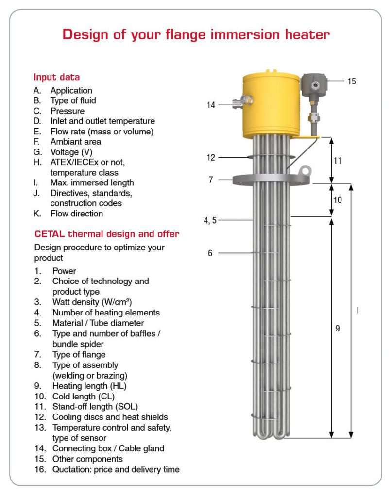
The watt density, tube diameter and the tube sheath are chosen to optimize the reliability and robustness (corrosion, temperature) of CETAL equipments.
Technologies
- Tubular heating element (most fo the cases)
- Heating rods into sleeve
Tube diameter & material
- Tube diameter: 6.5 / 8.5 / 10 / 13.5 / 16 mm
- Tube material:
- Stainless steel: AISI 321 (1.4541) / AISI 316L (1.4404) / AISI 309 (1.4828)
- Others: Incoloy 800 (1.4876) / Incoloy 825 (2.4858) / Inconel 600 (2.4816)
- Titanium
- Specific coating: TeflonTM (PTFE) / Halar
- Tube type: sealed tube, seamless tube (on request)
Manufacturing
- 100% of the components come high quality supplier from Europe
- 100% manufacture within CETAL factory
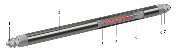
- Connection terminals
- Tube
- Insulation : magnesia oxyde (Mg O), to secure optimized heat transfer and electrical insulation.
- Resistance wire: Made of Nickel Chrome 80/20, it is the active part of the heating element (Joule effect)
- Cold length
- Sealing material: Keeps out external moisture. Different types (silicon, resins, cement) are used depending on the industrialapplication, the external medium and temperature.
- Output insulation: Made of steatite ou corundum, it provides dielectric insulation (creepage distance, distance in the air).
- All diameters (including very large sizes)
- NF EN 1092-1 (European standard, PN)
- NF EN 1759-1 (European standard, Class)
- ASME B16-5 (American standard)
- Others standards on request
- Material choice according to application and standards (carbon steel, stainless steel or others)
- TIG Welding : CETAL has QS and QMOS certification
- Brazing
- Non ATEX connecting box
- IP 54 / IP 66 / IP 67
- Material: painted steel, stainless steel, aluminium
- Polyamide or nickel-plated
- ATEX/IECEx connecting box
- Explosion-proof connecting box, aluminium, stainless steel or painted steel, Ex d IIC
- Stainless steel increased security enclosure,Ex e IIC
- Nickel-plated brass cable gland (stainless steel as option)
- Fluid temperature <110°C, no offset
- Fluid temperature >110°C, offset between the protecting box and the tank is recommended
- Temperature sensors (thermostat, limiter, thermocouple or PT100) in the medium (process control) or on the heating element (safety control), on the flange or in the connecting box.
- Voltage: VAC or VCC
- Cabling according to main voltage VAC/VCC 1PH + N or 3PH
- Power : a few Watt to several Megawatts
- Standard documentation
- Certificate of conformity to the order
- Heater wiring diagram
- Instruction manual
- On-request documentation
- Supplied according to directives, standard and construction code
- Welder qualifications (QS)
- Welding qualifications (QMOS)
- PED documentation
- Material certificate 3.1 acc. to NF EN 10204
- According to CE European directives and CE market (for Europe)
- ATEX/IECEx certificate for component or system
- EAC CU TR, c CSA us (NEC 505)
![]()
Electrical tests
- Power test by cold resistance measurement. Allowed tolerance: -5% and +10% of the nominal resistance value.
- Insulation test, direct voltage 500 V, mini cold value is > 100 Megohms
- Dielectric test, (2U + 1000 V) x 1,2 during 1 second
- The stray current and the hot dielectric rigidity can be measured on a sample at operating temperature (on request).
- 100% of the heating elements are tested before shipment (Final control)
Mechanical tests
- Visual inspection
- X-ray test (if required)
- Liquid penetrant test
- Pressure control test
Dimensional test
- Critical dimension are tested
Other tests / operations
- Helium test (on request)
- Degreasing
- Argon cleaning
Third party
- Third party inspection (on request)
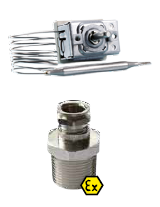
- Temperature control : Temperature sensors (thermostat, limiter, thermocouple or PT100) in the medium (process control) or on the heating element (safety control), on the flange or in the connecting box.
- Separate connecting box for temperature control out of the power connecting box
- Stainless steel material for ATEX/IECEx cable gland
- Space heaters against moisture inside the connecting box
- Coating for the connecting box customized specifications and colors
- Tropicalization: Adapted materials and components, heat-shrink insulated terminals, for extreme atmospheres (moisture, temperature)
- Insulation: according to design if needed
In addition to heater design, the use of specifically developed connection boxes allows to install the products in hazardous areas.
The increased safety protection mode “e” (EN60079-7) or the explosion-proof protection mode “d” (EN 60079-1), together with temperature control acc. to EN 60079-0, make it possible to operate the equipments in hazardous area (zone 1 and zone 2) for gases of the A-B-C groups.
Type of protection “d” explosion-proof connection box
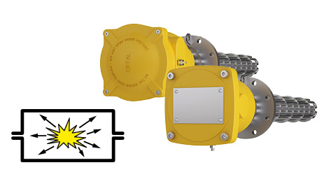
With this method, the housing (casing):
- Must contain the explosion within the enclosure
- Make sure that the ignition cannot reach the hazardous area
- Always keep an external temperature lower than the auto-ignition temperature of any surrounding
The following factors are selected depending on the internal free volume of the enclosure and the gas present in the area:
- Type of seal (cylindrical, flat, threaded)
- Seal length
- Gap length
The power and temperature control circuits can be accommodated in separate housings.
Type of protection “e” increased safety
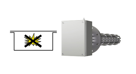
Method: To prevent the occurrence of any accidental ignition source (electric arcs, heating).
This mode of protection is achieved by:
- Selecting high-quality insulating material
- Defining the right creepage distances
- Ensuring the quality of electrical connection
- For all classes of gases and vapours
- Suitable for connection housings


