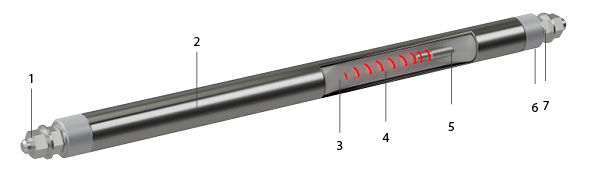
Customized ribbed heating elements
Product overview
- Power from 200 W – 10 kW or more
- Tubular heating elements in AISI 321 stainless steel equipped with zinc-coated fins
- Rectangular or round fins
- Mounting with crimped steel connector
- U-shaped terminals
- Well-designed for premises air heating or gas heating in natural or forced circulation
- Max. sheath tube temperature:
- 350°C for steel fins
- 600°C for stainless steel fins (option)
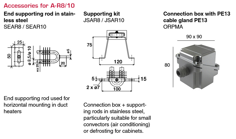
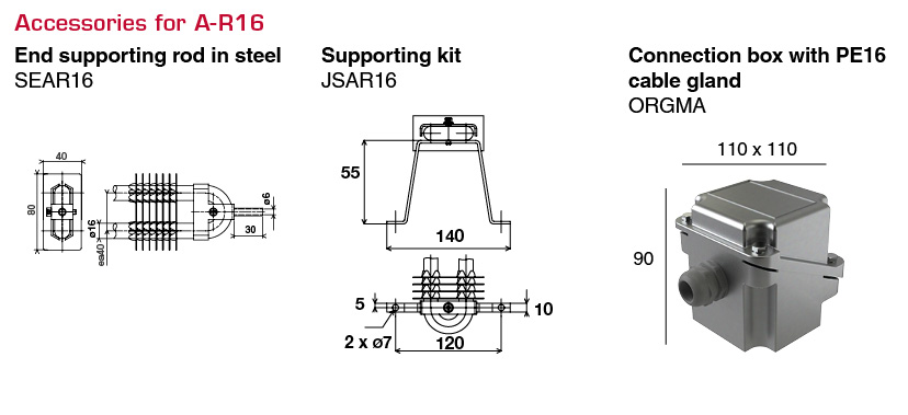
- Used for exemple in duct heaters
Advantages
- Reliability and robustness of the heating element. High-quality raw material.
- Different types of fins : rectangular, round, spiral fins
Operating conditions
- Hazardous areas (ATEX/IECEx) and NEC 505
- Onshore / offshore environment
Gas
- Air, max load 0.1 – 8W/cm² acc to sheath temp, material: 321 and speed (m/s)
- Non-corrosive gas
Technical description
The watt density, tube diameter and the tube sheath are chosen to optimize the reliability and robustness (corrosion, temperature) of CETAL equipments.
Technologies
- Tubular heating element
Tube diameter & material
- Tube diameter: 8.5 / 10 / 13,5 / 16 mm
- Tube material: Stainless steel AISI 304 or 321
- Tube type: sealed tube
Manufacturing
- 100% of the components come high quality supplier from Europe
- 100% manufacture within CETAL factory
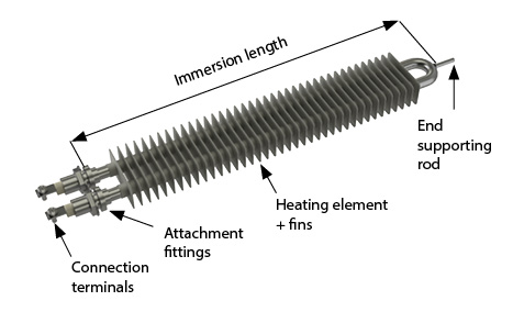
- Connection terminals
- Tube
- Insulation : magnesia oxyde (Mg O), to secure optimized heat transfer and electrical insulation.
- Resistance wire: Made of Nickel Chrome 80/20, it is the active part of the heating element (Joule effect)
- Cold length
- Sealing material: Keeps out external moisture. Different types (silicon, resins, cement) are used depending on the industrial application, the external medium and temperature
- Output insulation: Made of steatite ou corundum, it provides dielectric insulation (creepage distance, distance in the air).
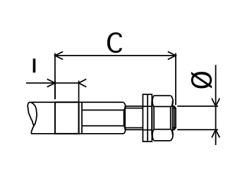
Type B 100
- THREADED STEEL OR STAINLESS STEEL ROD
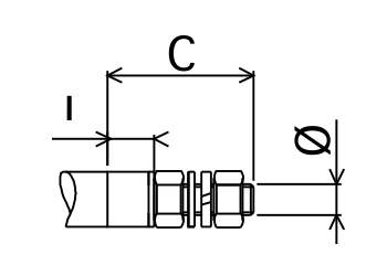
| Dimensions | Sheaths Ø | ||||||
| Ø mm | C | I | 6.5 | 8.5 | 10 | 13.5 | 16 |
| M4 x 0.7 | 20 | 5 | |||||
| M4 x 0.7 | 20 | 5 | |||||
| M4 x 0.7 | 20 | 5 | |||||
| M5 x 0.8 | 30 | 10 | |||||
| M5 x 0.8 | 30 | 10 | |||||
| M6 x 1 | 35 | 10 | |||||
| M6 x 1 | 35 | 10 | |||||
| M8 x 1.25 | 35 | 10 | |||||
| M8 x 1.25 | 35 | 10 | |||||
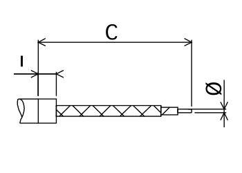
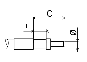
Type B 200
- PLAIN ROD
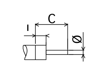
| Dimensions | Sheaths Ø | ||||||
| Ø mm | C | I | 6.5 | 8.5 | 10 | 13.5 | 16 |
| 2 | 20 | 5 | |||||
| 3.5 | 25 | 5 | |||||
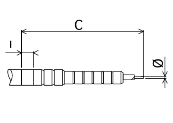
Type B 300
- BRAID OR CABLE
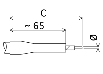
| Dimensions | Sheaths Ø | |||||
| section mm² | C | 6.5 | 8.5 | 10 | 13.5 | 16 |
| PVC INSOLATED COPPER CABLE H07VK 70°C | ||||||
| 1.5 | (1) | |||||
| 2.5 | (1) | |||||
| RUBBER INSOLATED COPPER H07RNF 85°C | ||||||
| 1.5 | (1) | |||||
| 2.5 | (1) | |||||
| 4 | (1) | |||||
| 1.5 | (1) | |||||
| 2.5 | (1) | |||||
| 4 | (1) | |||||
| 6 | (1) | |||||
| 10 | (1) | |||||
| SILICONE INSOLATED COPPER 180°C | ||||||
| 1.5 | (1) | |||||
| 2.5 | (1) | |||||
| 4 | (1) | |||||
| 6 | (1) | |||||
| GLASS BRAIDED COPPER 280°C | ||||||
| 1 | (1) | |||||
| 1.5 | (1) | |||||
| 2.5 | (1) | |||||
| 4 | (1) | |||||
| 6 | (1) | |||||
| INSOLATED NICKEL WIRE 700°C | ||||||
| 1.5 | (1) | |||||
| 2.5 | (1) | |||||
| 4 | (1) | |||||
| 6 | (1) | |||||
(1) Cable lenght go request
| Dimensions | Sheaths Ø | |||||
| section mm² | C | 6.5 | 8.5 | 10 | 13.5 | 16 |
| NICKEL BRAIDED NICKEL 350°C / 450°C | ||||||
| 1 | (1) | |||||
| 2.5 | (1) | |||||
| 2.5 | (1) | |||||
| 4 | (1) | |||||
| 6 | (1) | |||||
(1) Cable lenght go request
| Dimensions | Sheaths Ø | |||||
| section mm² | C | 6.5 | 8.5 | 10 | 13.5 | 16 |
| CERAMIC NICKEL WIRE | ||||||
| 1.5 | (1) | |||||
| 2.5 | (1) | |||||
(1) Cable lenght go request
Type B 400
- 6,35 TAB
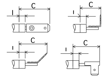
| Dimensions | Sheaths Ø | ||||
| Description | C | I | 6.5 | 8.5 | 10 |
| Straight single | 25 | 5 | |||
| carved single | 23 | 5 | |||
| Transverse single | 15 | 5 | |||
| Straight twin | 22 | 5 | |||
| Delta twin | 22 | 5 | |||
Type B 500
- FLAT TERMINAL
| Dimensions | Sheaths Ø | |||||
| C | I | 6.5 | 8.5 | 10 | 13.5 | 16 |
| 25 | 5 | |||||
| 30 | 10 | |||||
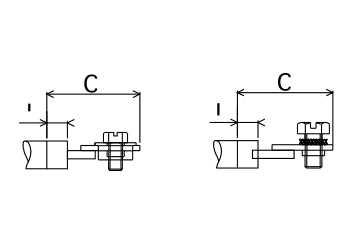
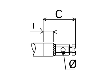
Type B 600
- THREADED TERMINAL
| Code | Dimensions | Sheaths Ø | ||||
| Ø mm | C | I | 6.5 | 8.5 | 10 | |
| LAITON : B 614-6 | M6 x 1 | 30 | 5 | |||
| INOX : B 623-6 | M6 x 1 | 21 | 5 | |||
Type B 700
- SCREW TYPE BRASS TERMINAL
| Dimensions | Sheaths Ø | |||
| C | I | 6.5 | 8.5 | 10 |
| 15 | 5 | |||
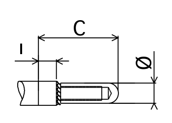
Type B 800
- BRAZABLE STEATITE
| Dimensions | Sheaths Ø | ||||||
| Ø mm | C | I | 6.5 | 8.5 | 10 | 13.5 | 16 |
| M 6 | 37 | 13 | |||||
| M 6 | 37 | 13 | |||||
| M 8 | 55 | 15 | |||||
| Use in humid conditions | watertight | ||||||
| temperature from – 60°C to + 200°C | |||||||
| defrosting resistance | |||||||
Type B 900
- BRASS PIN TERMINAL
| Dimensions | Sheaths Ø | ||||||
| Ø mm | C | I | 6.5 | 8.5 | 10 | 13.5 | 16 |
| 6 | 22 | 5 | |||||
| 6 | 22 | 5 | |||||
- Rectangular fins:
- tube diameter 8,5 & 10 mm: 50×25 mm in steel, zinc coated or stainless steel
- tube diameter 13,5 & 16 mm: 80×40 mm in steel, zinc coated or stainless steel
- Round fins:
- tube diameter 8,5 & 10 mm: 24 mm in zinc coated or stainless steel
- tube diameter 10 mm: 24 mm in stainless steel
- tube diameter 16 mm: 40 mm in zinc coated or stainless steel
- Spiral round fins:
- tube diameter 10 mm: 26 mm in stainless steel AISI 430
- The fins are fitted without clearance with the zinc coated or stainless steel fins
- Crimped or welded steel, stainless steel connectors
- Supply with washer and nuts
- According to CE European directives and CE market (for Europe)
- ATEX/IECEx certificate for component or system
- EAC CU TR, c CSA us (NEC 505)
![]()
Electrical tests
- Power test by cold resistance measurement. Allowed tolerance: -5% and +10% of the nominal resistance value.
- Insulation test, direct voltage 500V, mini cold value is > 100 Megohms
- Dielectric test, 2U + 1000V
- The stray current and the hot dielectric rigidity can be measured on a sample at operating temperature (on request).
100% of the heating elements are tested before shipment (final control)
Mechanical tests
- Visual inspection
Dimensional test
- Critical dimensions are tested