
Convectors
Product overview
- Power from 100W to ~10kW
- Voltage max. 680 V
- Galvanized steel frame or stainless steel
- Enamelled , steel, zinc coated or stainless steel fins
Advantages
- Large range of materials and options according to customer process and conditions of use
- Benefit from CETAL’s 50 years of experience as designer and manufacturer!
- Equipment available for use in hazardous areas or safe environment
- Robustness
Operating conditions
- Normal (non-ATEX)
- Hazardous areas (ATEX/IECEx) and NEC 505
- Extreme environments: – 60°C to + 80 °C
- Onshore / Offshore environment
- Salt atmosphere
Gas
- Air, max load 0.1 -8W/cm² according to sheath temperature, material: 321
- Non corrosive gas
Technical description
The Watt density, tube diameter and the tube sheath are chosen to optimize the reliability and robustness (corrosion, temperature) of CETAL equipments.
Technologies
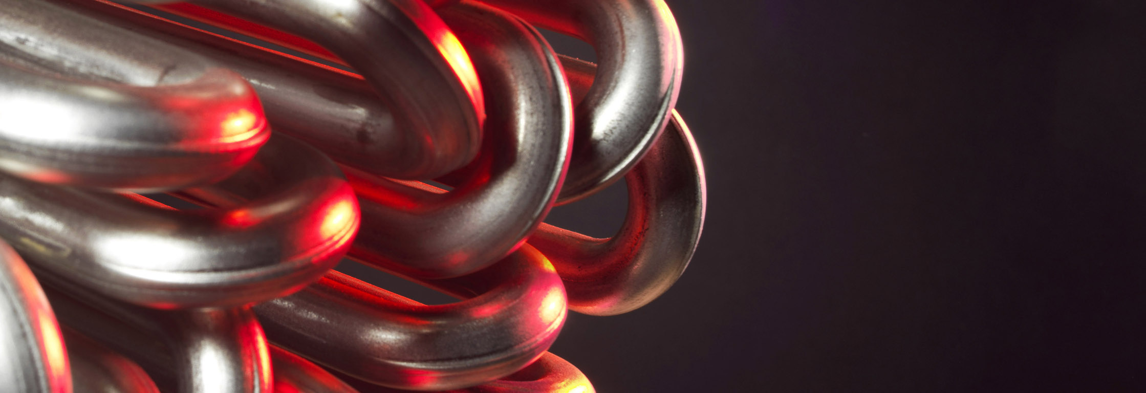
- Tubular heating element
- Ceramic heaters inside the ribbed tube.
Tube diameter & material
- Tube diameter: 8.5 / 10 / 13.5 /16 mm
- Tube material: Stainless steel: AISI 304 or 321
- Tube type: sealed tube
Manufacturing
- 100% of the components come from our high-quality suppliers from Europe
- 100% manufacturing in CETAL factory
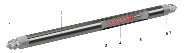
- Connection terminals
- Tube
- Insulation: magnesia oxyde (Mg O), to secure optimized heat transfer and electrical insulation.
- Resistance wire: Made of Nickel Chrome 80/20, it is the active part of the heating element (Joule effect)
- Cold length
- Sealing material: Keeps out external moisture. Different types (silicon, resins, cement) are used depending on the industrialapplication, the external medium and temperature.
- Output insulation: Made of steatite ou corundum, it provides dielectric insulation (creepage distance, distance in the air).
|
RAE Series |
RBAE Series |
||
|
According to EC type examination certification |
LCIE 01 ATEX 6042 X IECEx LCIE 15.0029X |
LCIE 01 ATEX 6042 X IECEx LCIE 15.0029X |
|
|
Type of heating elements |
Ribbed heating elements |
Ceramic core element |
|
|
Materials |
Partially open galvanized steel frame, or stainless steel, enamelled fins. The stainless steel version is recommanded for use in particular environments such as salt-water environment. |
Coated steel tube and fins |
|
|
Support and chassis |
Galvanized steel or stainless steel |
Painted steel |
|
|
ATEX/IECEx temperature class |
T3 / T4 |
T3 / T4* |
|
|
Ambient operating temperature |
– 50 °C ≤ Ta ≤ + 40° C |
||
|
Max. temperature on heating element |
+ 200 °C (T3) / + 135 °C (T4) at 40 °C ambient temperature |
||
|
Coupling |
500 W and 750 W versions: 230 V 1PH Other versions: 230 V 1PH or 400 V 3PH star or delta connection ** |
230 V 1PH, 400 V 3PH on demand |
|
|
ATEX/IECEx housing |
Type d ExdIIC, painted aluminium, RAL 1004 yellow paint finish |
Type e ExeIIC, stainless steel or painted steel including |
Type “d” ExdIIC, |
|
Options |
Integrated thermostat, stainless steel sleeve, |
||
|
|||
* on request
** other voltage on demand, max. 680 V
- Certified for operation in hazardous areas in zone 1/11 and 2/22
- EC-type examination certificate LCIE 01 ATEX 6042X
- IECEx Certificate of Conformity LCIE 15.0029X
- EAC & CU TR (former GOST)
![]()
Electrical tests
- Power test by cold resistance measurement. Allowed tolerance: -5% and +10% of the nominal resistance value.
- Insulationtest, direct voltage 500 V, mini cold value is > 100 Megohms
- Dielectric test, (2U + 1000 V) x 1,2 during 1 second
- The stray current and the hot dielectric rigidity can be measured on a sample at operating temperature (on request).
- 100% of the heating elements are tested before shipment (Final control)
Mechanical tests
- Visual inspection
Dimensional test
- Critical dimension are tested
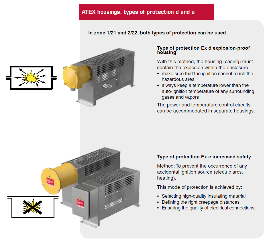
In addition to heater design, the use of specifically developed connection boxes allows to install the products in hazardous areas.
The increased safety protection mode “e” (EN60079-7) or the explosion-proof protection mode “d” (EN 60079-1), together with temperature control acc. to EN 60079-0, make it possible to operate the equipments in hazardous area (zone 1 and zone 2) for gases of the A-B-C groups.
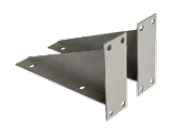 Wall mounting kit (optional)
A set of mounting brackets is available as option.


