
Bended heaters
CETAL can bend heating elements according to any shape, even the more complex
Product overview
- Power up to 30 kW per heating element
- Watt density from 0.1 to 20 w/cm²
- Voltage max. 750 V
Advantages
- Reliability and robustness of the heating element. High-quality raw material. 100% manufacturing in our factory.
- Large range of materials and options according to customer process and conditions of use.
- Benefit from CETAL’s 50 years of experience as designer and manufacturer!
Operating conditions
- Normal (non-ATEX)
- Hazardous areas (ATEX/IECEx) and NEC 505
- Fluid/solid: from – 270 °C (3 K) to 1000 °C
- Corrosive environment
Water
- Stagnant water, max load 8 – 12 W/cm², material: copper, 321, 316L
- Circulating water, max load 10 – 16 W/cm², material: copper, 316L, inc 800, inc 825
- Boric water, max load 8 W/cm², material: 316L
- Boiler water, max load 8 – 16W/cm², material: 316L, inc 800, inc 825
- Chlorated water, max load 6 W/cm², material: inc 825
- Sea water, max load 3,5 – 6 W/cm², material: inc 825, inc 600
- Demineralized water / deionized / distilled / Softened, max load 4 – 6 W/cm², material: 316L, inc 800, inc 825
- Domestic hot water, max load 4 – 8 W/cm², material: copper, 316L, inc 825
- Caustic water (2%, 10%, <30%, 70%), max load 2,3 – 7 W/cm², material: 316L, inc 825, inc 600
Oil
- Fuel oil pre-heating, light fuel oil, C fuel oil, max load 1 – 2 W/cm², material: 321, 316L
- Heavy fuel, max load 0.5 – 3.5 W/cm² acc to grade, material: 316L
- Gasoline, kerosene, max load 3.0 – 3.5 W/cm², material: 316L
- Machine oil SAE 10, 30, 40 & 50, max load 2,0 – 3.5 W/cm², material: 316L
- Mineral oil , max load 0.5 – 3.5 W/cm² acc to temp, material: 321, 316L
- Lube oil, max load 2.3 W/cm², material: 321, 316L
Acid & corrosive fluid
- Acetic acid, max load 6W/cm², material: 316L, inc 825
- Boric acid, max load 6W/cm², material: inc 825
- Chloric, hydrofluoric, nitric, sulphuric acide, max load 1,5W/cm², material: teflon coat
- Boric acid, max load 6W/cm², material: inc 825
- Alkaline bath, max load 6W/cm², material: 321 (no corrosive compound), 316L
- Phosphate bath, max load 4W/cm², material: 316L, inc 825
Glycol
- Ethylene glycol, propylene glycol, 4 to 8 W/cm² acc. to concentration, material: 321, 316L
Others
- Asphalt, tar, and other heavy or highly viscous compounds, max load 0.5 – 1.5W/cm², material: 316L
- Milk, max load 0.3W/cm², material: 316L
Gas
- Air, max load 0.1 – 8W/cm² acc to sheath temp, material: 321
- Circulating air, max load 0.1 – 8 W/cm² acc to sheath temp, material: 309
- Natural gas, max load 0.1 – 8 W/cm² acc to sheath temp, material: 321, 316L
- Argon, nitrogen, W/cm² acc to sheath temp, material: 321, 316L, inc 825, inc 600
- Propan, Butane, W/cm² acc to sheath temp, material: 321, 316L
- Oxygen, Hydrogen, W/cm² acc to sheath temp, material: 316L
Solids
- Aluminium, brass, bronze cast in, max load 4 – 15W/cm², material: 309
- Copper-nickel cast in, max load 5 – 10W/cm², material: 309
- Oxychloration, max load 3 W/cm², material: inc 800, inc 825
- Calcination, max load 3 W/cm², material: inc 800, inc 825
- HC regeneration, max load 2 W/cm², material: inc 800, inc 825
Technical description
The watt density, tube diameter and the tube sheath are chosen to optimize the reliability and robustness (corrosion, temperature) of CETAL equipments.
Technologies
- Tubular heating element
Tube diameter & material
- Tube diameter: 6.5 / 8.5 / 10 / 13.5 / 16 mm
- Tube material:
- Stainless steel: AISI 321 (1.4541) / AISI 316L (1.4404) / AISI 309 (1.4828)
- Others: Incoloy 800 (1.4876) / Incoloy 825 (2.4858) / Inconel 600 (2.4816)
- Titanium
- Specific coating: TeflonTM (PTFE) / Halar
- Tube type: sealed tube, seamless tube (on request)
Manufacturing
- 100% of the components come high quality supplier from Europe
- 100% manufacturing in CETAL factory
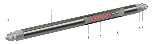
- Connection terminals
- Tube
- Insulation : magnesia oxyde (Mg O), to secure optimized heat transfer and electrical insulation.
- Resistance wire: Made of Nickel Chrome 80/20, it is the active part of the heating element (Joule effect)
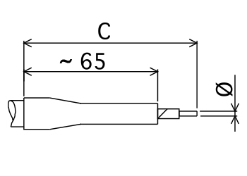
- Cold length
- Sealing material: Keeps out external moisture. Different types (silicon, resins, cement) are used depending on the industrial application, the external medium and temperature
- Output insulation: Made of steatite ou corundum, it provides dielectric insulation (creepage distance, distance in the air).
CETAL offer a large range non heating part / cold part to meeting any customer specification.
The table below shows the different cold part available by diameter and length.
| Tube Ø | 6 | |||||||||
|---|---|---|---|---|---|---|---|---|---|---|
| 8,5 | ||||||||||
| 10 | ||||||||||
| 13,5 | ||||||||||
| 16 | ||||||||||
| Ø tige de sortie | Ø 2 | Ø 3,5 | M4 x 0,7 | M5 x 0,8 | M6 x 1 | M8 x 1,25 | ||||
| Lg NCH | Matière Acier | Matière Inox | Matière Acier | Matière Inox | Matière Acier | Matière Inox | Matière Acier | Matière Inox | Matière Acier | |
| 35 | ||||||||||
| 40 | ||||||||||
| 45 | ||||||||||
| 55 | ||||||||||
| 75 | ||||||||||
| 65 | ||||||||||
| 95 | ||||||||||
| 105 | ||||||||||
| 135 | ||||||||||
| 150 | ||||||||||
| 180 | ||||||||||
| 205 | ||||||||||
| 200 | ||||||||||
| 225 | ||||||||||
| 235 | ||||||||||
| 260 | ||||||||||
| 300 | ||||||||||
| 330 | ||||||||||
| 365 | ||||||||||
| 415 | ||||||||||
| 420 | ||||||||||
| 445 | ||||||||||
| 500 | ||||||||||
| 505 | ||||||||||
| 530 | ||||||||||
| 620 | ||||||||||
| 775 | ||||||||||
| 800 | ||||||||||
| 1000 | ||||||||||
| 1340 | ||||||||||
| Materials | |||||||
| Copper | Austenitic steel | Nickel ally | |||||
| AISI code | 321 | 316 L | 309 S | INCOLOY 800 | INCOLOY 825 | INCONEL 600 | |
| DIN code | 1.4541 | 1.4404 | 1.4828 | 1.4876 | 2.4858 | 2.4816 | |
| Usuals diameters | |||||||
| 6,5 | |||||||
| 8,5 | |||||||
| 10 | |||||||
| 13,5 | (1) | ||||||
| 16 | (1) | (1) | |||||
| limit temperature of use | |||||||
| 250° C in the air | 750° C | 750° C | 1000° C | 950° C | 950° C | 950° C | |
(1) Stainless steel tube on stock
| Tube diameter | Max voltage |
| 6.5 | 400V |
| 8.5 | 415V |
| 10 | 500V |
| 13.5 | 690V |
| 16 | 750V |
- Wire restance tolerance: -5% and +10% of the nominal resistance value
- Power tolerance < 100W: -/+10%
- Power tolerance > 100W: +5% – 10%
|
Sheaths |
Very high quality rolled, welded or seamless tube manufactured and inspected according to standards ASTM-DIN ou NFA 49-147 |
|||
|
Forming |
The heating elements are available in a variety of shapes adapted to the use circumstances defined in the specifications or by the customer |
|||
|
Tolerances |
Diameter: |
6,5 ± 0.1 mm |
13,5 ± 0.1 mm |
|
|
8,5 ± 0.1 mm |
16 ± 0.1 mm |
|||
|
10 ± 0.1 mm |
||||
|
Length: |
± 1 % with + 5mm minimum |
|||
|
Standard material: |
the dimensions in the table are maximal dimensions intended to prevent assembly problems |
|||
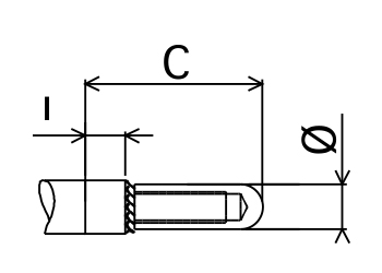
Type B 100
- THREADED STEEL OR STAINLESS STEEL ROD
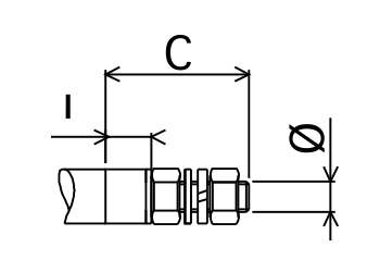
| Dimensions | Sheaths Ø | ||||||
| Ø mm | C | I | 6.5 | 8.5 | 10 | 13.5 | 16 |
| M4 x 0.7 | 20 | 5 | |||||
| M4 x 0.7 | 20 | 5 | |||||
| M4 x 0.7 | 20 | 5 | |||||
| M5 x 0.8 | 30 | 10 | |||||
| M5 x 0.8 | 30 | 10 | |||||
| M6 x 1 | 35 | 10 | |||||
| M6 x 1 | 35 | 10 | |||||
| M8 x 1.25 | 35 | 10 | |||||
| M8 x 1.25 | 35 | 10 | |||||
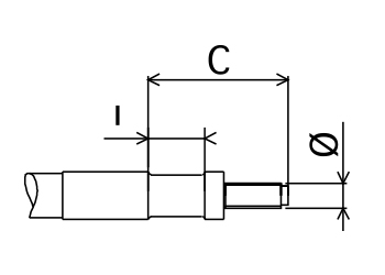
Type B 200
- PLAIN ROD
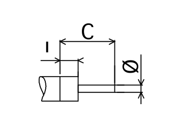
| Dimensions | Sheaths Ø | ||||||
| Ø mm | C | I | 6.5 | 8.5 | 10 | 13.5 | 16 |
| 2 | 20 | 5 | |||||
| 3.5 | 25 | 5 | |||||
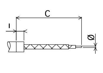
Type B 300
- BRAID OR CABLE
| Dimensions | Sheaths Ø | |||||
| section mm² | C | 6.5 | 8.5 | 10 | 13.5 | 16 |
| PVC INSOLATED COPPER CABLE H07VK 70°C | ||||||
| 1.5 | (1) | |||||
| 2.5 | (1) | |||||
| RUBBER INSOLATED COPPER H07RNF 85°C | ||||||
| 1.5 | (1) | |||||
| 2.5 | (1) | |||||
| 4 | (1) | |||||
| 1.5 | (1) | |||||
| 2.5 | (1) | |||||
| 4 | (1) | |||||
| 6 | (1) | |||||
| 10 | (1) | |||||
| SILICONE INSOLATED COPPER 180°C | ||||||
| 1.5 | (1) | |||||
| 2.5 | (1) | |||||
| 4 | (1) | |||||
| 6 | (1) | |||||
| GLASS BRAIDED COPPER 280°C | ||||||
| 1 | (1) | |||||
| 1.5 | (1) | |||||
| 2.5 | (1) | |||||
| 4 | (1) | |||||
| 6 | (1) | |||||
| INSOLATED NICKEL WIRE 700°C | ||||||
| 1.5 | (1) | |||||
| 2.5 | (1) | |||||
| 4 | (1) | |||||
| 6 | (1) | |||||
(1) Cable lenght go request
| Dimensions | Sheaths Ø | |||||
| section mm² | C | 6.5 | 8.5 | 10 | 13.5 | 16 |
| NICKEL BRAIDED NICKEL 350°C / 450°C | ||||||
| 1 | (1) | |||||
| 2.5 | (1) | |||||
| 2.5 | (1) | |||||
| 4 | (1) | |||||
| 6 | (1) | |||||
(1) Cable lenght go request
| Dimensions | Sheaths Ø | |||||
| section mm² | C | 6.5 | 8.5 | 10 | 13.5 | 16 |
| CERAMIC NICKEL WIRE | ||||||
| 1.5 | (1) | |||||
| 2.5 | (1) | |||||
(1) Cable lenght go request
Type B 400
- 6,35 TAB
| Dimensions | Sheaths Ø | ||||
| Description | C | I | 6.5 | 8.5 | 10 |
| Straight single | 25 | 5 | |||
| carved single | 23 | 5 | |||
| Transverse single | 15 | 5 | |||
| Straight twin | 22 | 5 | |||
| Delta twin | 22 | 5 | |||
Type B 500
- FLAT TERMINAL
| Dimensions | Sheaths Ø | |||||
| C | I | 6.5 | 8.5 | 10 | 13.5 | 16 |
| 25 | 5 | |||||
| 30 | 10 | |||||
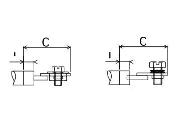
Type B 600
- THREADED TERMINAL
| Code | Dimensions | Sheaths Ø | ||||
| Ø mm | C | I | 6.5 | 8.5 | 10 | |
| LAITON : B 614-6 | M6 x 1 | 30 | 5 | |||
| INOX : B 623-6 | M6 x 1 | 21 | 5 | |||
Type B 700
- SCREW TYPE BRASS TERMINAL
| Dimensions | Sheaths Ø | |||
| C | I | 6.5 | 8.5 | 10 |
| 15 | 5 | |||
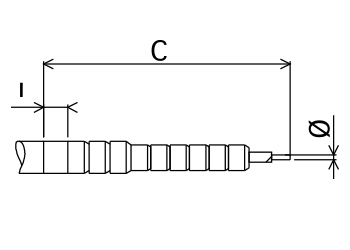
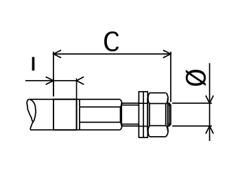
Type B 800
- BRAZABLE STEATITE
| Dimensions | Sheaths Ø | ||||||
| Ø mm | C | I | 6.5 | 8.5 | 10 | 13.5 | 16 |
| M 6 | 37 | 13 | |||||
| M 6 | 37 | 13 | |||||
| M 8 | 55 | 15 | |||||
| Use in humid conditions | watertight | ||||||
| temperature from – 60°C to + 200°C | |||||||
| defrosting resistance | |||||||
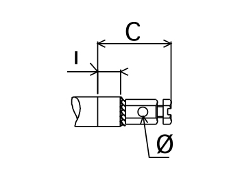
Type B 900
- BRASS PIN TERMINAL
| Dimensions | Sheaths Ø | ||||||
| Ø mm | C | I | 6.5 | 8.5 | 10 | 13.5 | 16 |
| 6 | 22 | 5 | |||||
| 6 | 22 | 5 | |||||
r = minimum bending radius
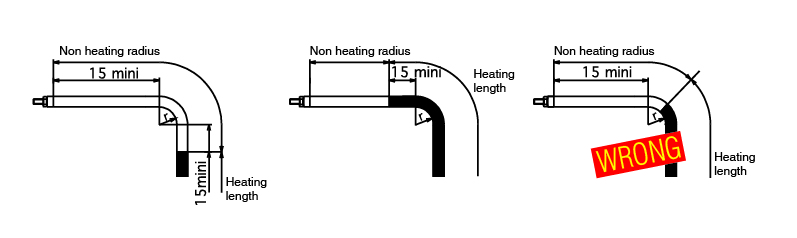
The heating part cannot in any circumstance start in the bending radius. Its starting point must always be located at least 15 mm before or after the bend.
The minimum bending diameter depends on the sheath material (see table)
| Sheaths Ø | 6.5 | 8.5 | 10 | 13.5/16 |
| Copper | 8.5 | 9 | 12 | 20 |
| Stainless steel | 7.5 | 9 | 11 | 20 |
| Incoloy | 11 | 17.5 | 18.5 | 30 |
| Inconel | 20 | 40 |
![]()
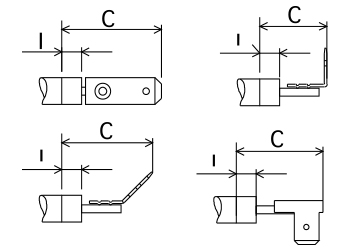
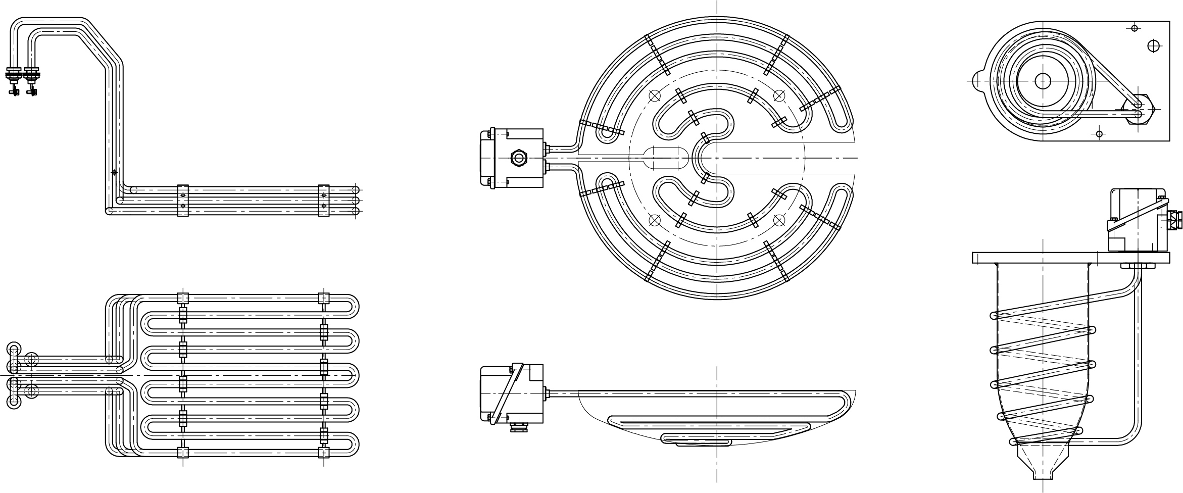
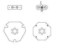
Realization examples
Connector
Heating elements with such connectors are supplied with nuts and seals (type 300)
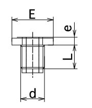
| Material | Dimensions | Sheath | |||
| d | E | e | L | Ø | |
| S. steel | M10 x 1 | R14 | 3 | 15 | 6.5 |
| Brass | M10 x 1 | R14 | 3 | 15 | 6.5 |
| Brass | M10 x 1 | R15 | 3 | 12 | 6.5 |
| Brass | M12 x 1 | R17 | 4 | 12 | 8.5 |
| S. steel | M12 x 1 | R18 | 4 | 12 | 6.5-8.5 |
| Brass | M12 x 1 | R18 | 4 | 12 | 6.5-8.5 |
| Steel | M12 x 1 | R18 | 4 | 12 | 6.5-8.5 |
| Brass | G 1/4” | H19 | 4 | 14 | 8.5 |
| Brass | M14 x 1,5 | R20 | 4 | 14 | 8.5-10 |
| Brass | M14 x 1,5 | R20 | 4 | 20 | 8.5-10 |
| Steel | M14 x 1,5 | R20 | 4 | 14 | 8.5-10 |
| Steel | M14 x 1,5 | R20 | 4 | 20 | 8.5-10 |
| S. steel | M14 x 1,5 | R20 | 4 | 16 | 8.5-10 |
| Brass | M16 x 1,5 | R22 | 4 | 17 | 8.5-10 |
| Steel | M16 x 1,5 | R23 | 6 | 45 | 10 |
| Brass | M20 x 1,5 | R27 | 5 | 20 | 13.5 |
| Steel | M20 x 1,5 | R27 | 5 | 20 | 13.5 |
| S. steel | M20 x 1,5 | R27 | 5 | 20 | 13.5 |
| Brass | M24 x 1,5 | R32 | 5 | 20 | 16 |
| Steel | M24 x 1,5 | R32 | 5 | 20 | 16 |
| S. steel | M24 x 1,5 | R32 | 5 | 22 | 16 |
Flange
Carbon steel or stainless steel, cut or deep-drawn, 1-5 mm thick
- According to CE European directives and CE market (for Europe)
- ATEX/IECEx certificate for component or system
- EAC CU TR, c CSA us (NEC 505)
![]()
Electrical tests
- Power test by cold resistance measurement. Allowed tolerance: -5% and +10% of the nominal resistance value.
- Insulationtest, direct voltage 500 V, mini cold value is > 100 Megohms
- Dielectric test, (2U + 1000 V) x 1,2 during 1 second
- The stray current and the hot dielectric rigidity can be measured on a sample at operating temperature (on request).
- 100% of the heating elements are tested before shipment (final control)
Mechanical tests
- Visual inspection
- X-ray test (if required)
Dimensional test
- Critical dimension are tested
- Marking: specific customer marking on each heating element
- Specific connection terminals (on request)
- Fixing part such as connectors (on request)
CETAL delivers bended heating elements to many customers in different industries where the reliability and the quality are a must.
The heating element being the active part (“engine”) of the final product or within the customer process, our customers make the choice of reliability!

