parallax background

CETALpedia

The value of a man should be seen in what he gives and not in what he is able to receive.

Albert Einstein

Over the last 50 years, CETAL has built an extensive experience on heating elements, heat exchange and associated technologies.

The purpose of CETALpedia is to provide access to the key information when it comes to:

In any case, do not hesitate to contact our CETAL engineers and experts to find the best solutions for your project.

TECHNICAL DATABASE

Substance Density (kg/dm³) Specific Heat (kcal/kg°C)
Acetic Acid 1,05 0,522
Acetone 0,79 0,514
Allyl Alcohol 0,85 0,665
Ammonia 0,70 1,099
Amyl Alcohol 0,82 0,65
Aniline 1,02 0,512
Bromine 3,12 0,107
Butyl Alcohol 0,81 0,563
Butyric Acid 0,96 0,515
Carbolic Acid (Phenol) 1,07 0,561
Carbon Disulfide 1,26 0,24
Carbon Tetrachloride 1,59 0,201
Caustic Soda (50% Solution) 1,53 0,78
Decane Ether 0,73 0,5
Di-ethyl 0,71 0,541
Ether 0,74 0,503
Ethyl Acetate 0,84 0,468
Ethyl Alcohol 0,79 0,68
Ethyl Bromide 1,45 0,215
Ethyl Chloride 0,90 0,368
Ethyl Iodide 1,93 0,161
Ethylene Glycol 1,11 0,555
Ethylene Bromide 2,19 0,173
Ethylene Chloride 1,15 0,294
Formic Acid 1,22 0,526
Glycerin 1,26 0,576
Heat Transfer Fluids
Dowtherm A 1,06 0,377
Dowtherm G 1,05 0,377
Mobiltherm 603 0,86 0,592
Therminol VP-1 1,06 0,377
Heptane 0,68 0,532
Hexane 0,66 0,6
Linseed Oil 0,93 0,44
Methyl Acetate 0,93 0,468
Methyl Alcohol 0,79 0,601
Methyl Iodide 2,28
Nitric Acid -100% 1,51 0,42
Nitrobenzene 1,21 0,35
Octane 0,71 0,51
Olive Oil 0,92 0,471
Pentane 0,63 0,558
Petroleum Products 0,00 0
Asphalt 1,00 0,42
Benzene (Benzol) 0,88 0,412
Kerosene 0,80 0,5
Fuel Oil #6 0,94 0,41
Gasoline 0,66 0,5
Lube Oils 0,89 0,43
Naphthalene 1,14 0,4
Paraffin (Melted) 0,71 0,71
Toluene 0,87 0,404
Propionic Acid 0,99 0,473
Propyl Alcohol 0,80 0,57
Soy Bean Oil 0,92 0,28
Sulfur (Melted) 0,23 0,234
Sulfuric Acid -100% 1,83 0,344
Tallow (Lard) 0,94 0,64
Turpentine 0,87 0,42
Water 1,00 1
Xylene (Ortho) 0,88 0,411
Substance Density (kg/m³) Specific Heat (kcal/kg°C)
Acetylene 1,17 0,38
Air 1,29 0,24
Ammonia 0,83 0,52
Argon 1,78 0,12
Butane-iso 2,76
Butane-n 2,59
Carbon Dioxide 1,97 0,20
Carbon Monoxide 1,25 0,24
Chlorine 3,20 0,11
Chlorodifl uoromethane (F-22) 4,98 0,15
Chloroform 0,14
Cyanogen 2,41 0,41
Dichlorodifl uoromethane (F-22) 5,67 0,14
Ethane 1,45 0,39
Ethyl Chloride 3,09 0,28
Ethylene 1,35 0,40
Fluorine 1,83 0,18
Helium 0,18 1,25
Hydrogen 0,10 3,41
Hydrogen Bromide 3,92 0,08
Hydrogen Chloride 1,76 0,19
Hydrogen Fluoride 0,92
Hydrogen Iodide 6,12 0,06
Hydrogen Sulfide 1,66 0,25
Methane 0,77 0,59
Methyl Chloride 2,45 0,24
Methyl Ether 2,26
Methyl Fluoride 1,66
Neon 0,97
Nitric Oxide 1,34 0,23
Nitrogen 1,26 0,24
Nitrous Oxide 2,12 0,21
Oxygen 1,43 0,22
Phosphine 1,64
Propane 2,17
Silicone Tetrafl uoride 5,04
Sulfur Dioxide 2,86 0,15
Water Vapor 0,64 0,48
Xenon 6,29
Temperature
  • K (Kelvin) = 273 + °C (Celsius)
Pressure – SI unit : Pa (Pascal) = N/m²
  • 1 bar =  100.000 Pa
  • 1 bar = 1,019 kg/cm²
  • 1 bar = 0,9869 atm
  • 1 atm = 1,0133 bar
Heat – SI Unit : J (Joule)
  • 1 J = 0,2388 cal
  • 1 cal = 4,18 J
  • 1 KWh = 3600 KJ
Length – SI Unit : m (meter)
  • 1 m = 3,281 ft = 39,37 in
  • 1 foot (ft) = 30,48 cm = 12 in
  • 1 inch (in) = 2,54 cm
Surface – SI Unit : m²
  • cm²= 0,1550 sqin
  • sqin = 6,452 cm²
  • sqfoot = 929 cm² = 144 sqin
Watt density
  • 1 W/cm² = 6,452 W/sqin
  • 1 W/sqin  = 0,155 W/cm²
Volume – SI unit : m³
  • 1 dm³ = 1 litre = 0,0353 cuft
  • 1 cuin = 16,387 cm³
Mass – SI Unit : kg
Flowrate m³/s
  • Aeraulics : 1 CFM (cubic feet per minute) = 1,699 m³/h
  • Water : 1 GPM (gallon per minute) = 227,712 l/h
Specific heat – SI unit : J/kg
  • 1 cal/gr = 4184 J/kg
Power – SI unit: W (Watt)
  • 1 VA (volt.ampère) = 1 W
  • 1 cal/s = 4,1874 W

OPTIMIZED PRODUCT DESIGN

  • Thermal power: Pth = Qm x Cp x ∆T
  • Required power: Pu = (Pth + loss heat) x 1.1
  • Installed power: Pi = Pu x (1 + voltage tolerance)²
  1. Watt density on tube sheath
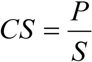
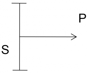
Watt density CS

P = Power in W
S = Surface in cm²
CS = watt density in en W/cm²
SP
  1. Tube sheath T°C
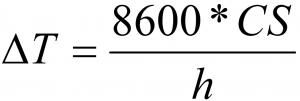
Tube sheath

ΔT = T°C gap between tube sheath and medium in  °C
CS = watt density in en W/cm²
h = heat exchange coefficient in kcal/h*m²*°C

  1. T°C gap between wire and tube sheath
Temperature gap between wire

ΔT = T°C gap between wire and tube sheath in °C
P = Power from D1 to D2 in kW
D1 and D2 internal and external diameter
λ = conduction coefficient in kcal/h*m*°C
L = cylinder length in m

CETAL engineers and expert define the watt density through an heat exchange software allowing to take into account all parameters.

CETAL software can effect detailed heat exchange calculations, the key outputs are:

  • Wire temperature
  • Tubular sheat tube temperature
  • Watt density
  • Pressure loss
  • Heat exchange coefficient

For basic design, please find below some references sorted by fluids.

Water

  • Stagnant water, max load 8 – 12 W/cm², material: copper, 321, 316L
  • Circulating water, max load 10 – 16 W/cm², material: copper, 316L, inc 800, inc 825
  • Boric water, max load 8 W/cm², material: 316L
  • Boiler water, max load 8 – 16W/cm², material: 316L, inc 800, inc 825
  • Chlorated water, max load 6 W/cm², material: inc 825
  • Sea water, max load 3,5 – 6 W/cm², material: inc 825, inc 600
  • Demineralized water / deionized / distilled / softened, max load 4 – 6 W/cm², material: 316L, inc 800, inc 825
  • Domestic hot water, max load 4 – 8 W/cm², material: copper, 316L, inc 825
  • Caustic water (2%, 10%, <30%, 70%), max load 2,3 – 7 W/cm², material: 316L, inc 825, inc 600

Oil

  • Fuel oil pre-heating, light fuel oil, C fuel oil, max load 1 – 2 W/cm², material: 321, 316L
  • Heavy fuel, max load 0,5 – 3,5 W/cm² acc to grade, material: 316L
  • Gasoline, kerosene, max load 3,0 – 3,5 W/cm², material: 316L
  • Machine oil SAE 10, 30, 40 & 50, max load 2,0 – 3,5 W/cm², material: 316L
  • Mineral oil , max load 0,5 – 3,5 W/cm² acc to temp, material: 321, 316L
  • Lube oil, max load 2,3 W/cm², material: 321, 316L

 Acid & corrosive fluid

  • Acetic acid, max load 6W/cm², material: 316L, inc 825
  • Boric acid, max load 6W/cm², material: inc 825
  • Chloric, hydrofluoric, nitric, sulphuric acide, max load 1,5W/cm², material: teflon coat
  • Boric acide, max load 6W/cm², material: inc 825
  • Alkaline bath, max load 6W/cm², material: 321 (no corrosive compound), 316L
  • Phosphate bath, max load 4W/cm², material: 316L, inc 825

Glycol

  • Ethylene glycol, propylene glycol, 4 to 8 W/cm² acc. to concentration, material: 321, 316L

Others

  • Asphalt, tar, and other heavy or highly viscous compounds, max load 0,5 – 1,5W/cm², material: 316L
  • Milk, max load 0,3W/cm², material: 316L

Gas

  • Air, max load 0,1 – 8W/cm² acc. to sheath temp, material: 321
  • Circulating air, max load 0,1 – 8 W/cm² acc. to sheath temp, material: 309
  • Natural gas, max load 0,1 – 8 W/cm² acc. to sheath temp, material: 321, 316L
  • Argon, nitrogen, W/cm² acc. to sheath temp, material: 321, 316L, inc 825, inc 600
  • Propan, Butane, W/cm² acc. to sheath temp, material: 321, 316L
  • Oxygen, Hydrogen, W/cm² acc. to sheath temp, material: 316L

Solids

  • Aluminium, brass, bronze cast in, max load 4 – 15W/cm², material: 309
  • Copper-nickel cast in, max load 5 – 10W/cm², material: 309
  • Oxychloration, max load 3 W/cm², material: inc 800, inc 825
  • Calcination, max load 3 W/cm², material: inc 800, inc 825
Inputs

  • ATEX or Not
  • Fluid type
  • Pressure (in bars)
  • T°C In and Out (in °C)
  • Flow rate (kg/h or Nm3/h)
  • Surroundings
  • Voltage (V)
  • Standards?
  Outputs

  • Power
  • Watt density
  • Tube sheath material & Ø
  • Product type and technology
  • Dimension (HL, CL, SOL)
  • Control and safety
  • Components choice
  • Price & leadtime

CETAL Solutions

Issues

Solutions

  • Loss of insulation
  • Humidity
  • Current leakage
  • Manufacturing process
  • Raw Material. Proprietary
  • CETAL R&D
  • Lack of power triggers disconnect
  • Overheat protection
  • Process failure
  • Mastering of heat exchange design
  • Output rods overheating
  • Destruction of sealing material
  • Heater failure
  • Proprietary rod design
  • Corrosion sheath tube
  • Thermal & Chemical
  • CETAL manufacturing process
  • Sheath tube proprietary design
  • Raw material
  • Wire fusion destruction
  • Mastering of wire T°C
  • Raw material
  • Hotspot = heater failure
  • Detailed control manufacturing process
  • Humidity / corrosion connection box
  • Connection box IP 66/67
  • CETAL packaging

Frequently Asked Questions

  • CETAL always advises or requires that the flow of the product through the heater be controlled.
  • A flow meter, or a low flow safety switch should be set on the piping upstream of the heater, on site. CETAL Local Control Panel, always foresee to get this low flow safety contact, for tripping the heater power, in case of too low flow.
  • CETAL always uses strong wooden crates for the heater and panel, packed in MIL133 sealed bag with dessicant, for export packing.
  • This is to avoid electrical parts being exposed to humidity condensation during transportation, and heater showing low isolation value after long-time exposure to humidity.
  • All spare parts are packed in the same manner, in separate wooden cases, packed in sealed bags, with number of drying bags calculated upon volume and storage time.
  • Woodens cases must be stored in a dry, ventilated warehouse, and stacked in storage place, or overloaded by cases stacked on top of them.

Basic maintenance actions to be taken are:

  • Check every year the ohmic value of the heater banks between phases.
  • Check insulation value between each phase and earth, and between phases.
  • Check the pressure drop through the heater at max flow and nominal outlet temperature, a pressure drop increase is a sign of caulking, cocking, clogging of fluid on the heating element bundle.
  • From long experience with many Oil&Gas companies, CETAL always includes at least one over-temperature sensor on each power step for each heating bundle. Most of time two.
  • The sensors are located on the upper part of the bundle , on the heating element wall, at the highest anticipated temperature area (near the fluid outlet nozzle commonly).
  • CETAL  recommands the use of duplex sensor to have one working, one in spare for each safety sensor.
  • HART protocol, Smart 4-20mA transmitters can be added, upon request, to allow in-situ checking, and setting.
  • To avoid power tripping of the heater in case of quick flow reduction, CETAL advices to monitor the heater power by a Thyristor stack , with fast response to signal change. Cetal also uses two alarm level high temperature switches , the first level initiating alarm, cutting the thyristor input, signal, the second tripping the main power .
  • For gas heaters in Oil&Gas field, CETAL always recommands a welding assembly preventing gas to be able to enter in the heater connection box. Thus, the gas can never enter the connection box and cause an explosion.
  • A gas detector in Ex connection box is not required by CETAL, due to our proven safe design.
  • CETAL, with its 50 year experience in heater design, selects the raw tube material for each type of fluid (gas or liquid), their composition (acid, sulphurous, fatty, crude, etc), the process conditions, the temperature level.
  • For heating elements with a diameter 16mm (final diameter), CETAL works only with a tube thickness of 1.1 mm to increase lifetime (corrosion resistance) and improve welding quality.
  • Raw tubes are supplied from European countries or USA, with Mill test certificates, commonly used material are Austenitic stainless steel from 304L to 310 grade, Incoloy 800, 825, Inconel 600, 625.
  • CETAL manufactures 100% of its heating elements.
  • 100% of the heating elements are checked before delivery.
  • First step of heating element manufacturing is to check, clean, cut the raw tubes at length.
  • We prepare the resistance heating wire on the winding using a dedicated tooling, ensuring a regular pitch, and cylindrical coil, with mastered allowance.
  • Degreasing and welding of heating wire on the clod end ensuring a perfect electrical continuity, with the cold end selected upon max. allowable current.
  • Centering of wire in the tube, and filling by means of special Magnesia filling equipment, ensuring good homogeneity on the whole length of element. Cap ends assy.
  • Rolling in pass of the tube, to ensure hardness, heat treatment for stress removal, in controlled gas environment. Bending in U.
  • Usual heating element outer diameter made : 6.5, 8.5, 10, 13.5, 16 mm.
  • All raw tubes are procured in fully annealed, normalized condition. After MgO filling, sealing, rolling in passes, the heating elements go for heat treatment (100% of the tube) to remove all stresses for bending, flattening (depending on tube diameter and material) and avoid corrosion.
  • CETAL has developed an internal heat exchange calculation software, ensuring that the maximal allowable fluid film temperature is never reached, even at the lowest process flow and highest fluid outlet temperature.
  • This software calculates the required heating element surface to have the best and safest heat exchange between heating element and fluid, which gives the maximal heat flux, upon the requested power.
  • This maximal heat flux depends on the type of fluid (density, viscosity, heat capacity, thermal conductivity), its flow, pressure ( for gases), and temperatures.
  • Heat flux on heating element, diameter, temperature, allows to select the most suitable heating wire for long and secure heater life.